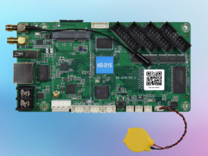
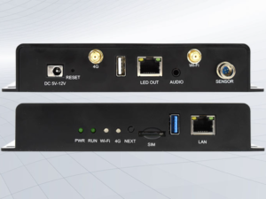
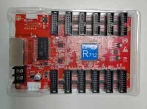
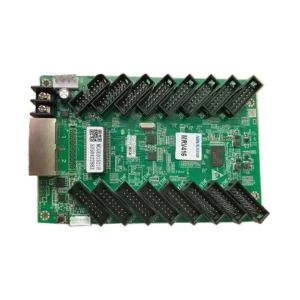
HUIDU 712 RECEIVING CARD
$10
— OR —
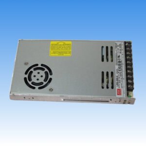
1.Overview R712isanLEDdisplayreceivingcardthatsupportsbothsynchronousandasynchronouscontrolsystem,no needHUBadapterboard. It isequippedwith12*HUB75Einterfaceonboard,withagoodstability,themaximum loadingcapacityis262,144pixels. 2. Parameters Features Parameters Withsendingcard Dual-modesendingbox,Asynchronoussendingcard,Synchronoussendingcard, VideoprocessorofVPseries. Moduletype CompatiblewithallcommonICmodule,supportedmostPWMICmodule. Scanmode Supportsanyscanningmethodfromstaticto1/128scan Communication method GigabitEthernet Controlrange Maximumloadingcapacity:262,144pixels (512*512) Recommendedloadingcapacity:conventionalchip128*1024pixels,PWMchip 256*1024pixels Note:Theactual loadingcapacityisrelatedtothenumberofHUBports/module resolution. Multi-cardconnection Receivingcardcanbeput inanysequence Grayscale 256~65536 Smartsetting Afewsimplestepstocompletethesmartsettings,throughthescreenlayoutcanbe set togowithanyalignmentof thescreenunitboard Testfunctions Receivingcardintegratedscreentest function,Testdisplaybrightnessuniformity anddisplaymoduleflatness. Communication distance SuperCat5,Cat6networkcablewithin80meters Port DC5VPower*2,1GbpsEthernetport*2,HUB75E*12 Inputvoltage 4.0V-5.5V Power 5W 3. InterfaceDescription No. Interface Description 1 Testbutton Usedtotestdisplaybrightnessuniformityanddisplaymoduleflatness. 2 Workindicator RANflashestoindicatethat thecontrolcardisrunningnormally.LAN flashesquicklytoindicatethatGigabithasbeenrecognizedanddatais beingreceived. 3 GigabitEthernetport Usedtoconnect thesendingcardorreceivingcard, thesametwonetwork portsareinterchangeable. 4 Power interface Canbeaccessedwith4.0V~5.5VDCvoltage. 5 Power interface Canbeaccessedwith4.0V~5.5VDCvoltage. 6 Flatcableinterface 12HUB75Einterface,connect totheLEDmodulesbyflatcable. 4. TechnicalParameters Item Parametervalue RatedVoltage(V) DC4.0V-5.5V WorkingTemperature(℃)-40℃~80℃ WorkingEnvironmentHumidity(%RH) 0~90%RH StorageEnvironmentHumidity(%RH) 0~90%RH Netweight(g) ≈91g Precautions: 1)Ensurethesystemlong-termstablerunning,pleaseusethestandardpowersupply. 2)Pleasedonotoperatewithelectricity 3)Duetotheproductionbatchandotherreasons, theremaybeaslighterrorbetweenthephotoandthereal thing. If indoubt,pleaseconfirmwithus
Put the circuit board in the fixture and then place it under a gravity tool to flatten it to the same level.
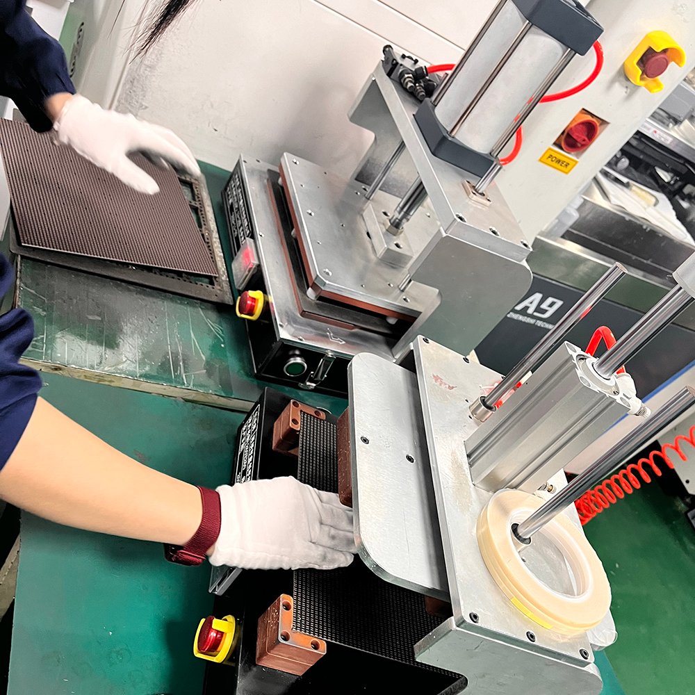
Use a tin brushing machine to evenly brush solder paste on the IC or lamp positions.
.
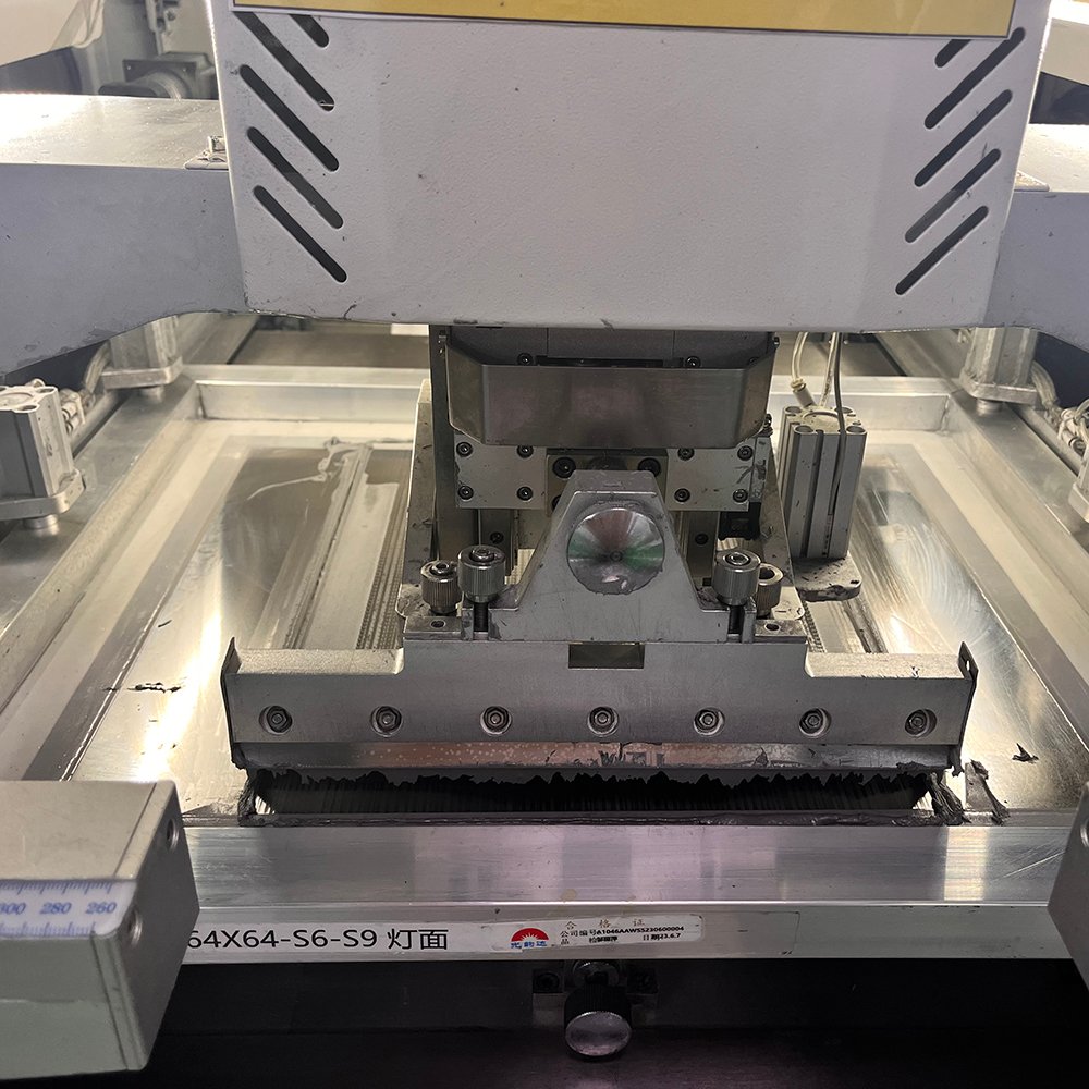
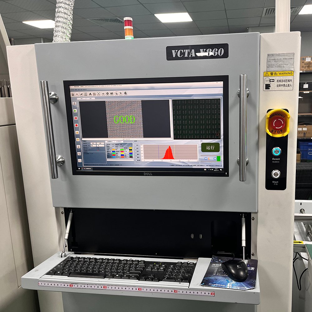
To ensure quality assurance, use testing machines to check if the solder injection points on the circuit board have been coated with solder paste.
high-speed SMT machine can produce up to 1000 LED modules per day, ensuring timely delivery for our customers.
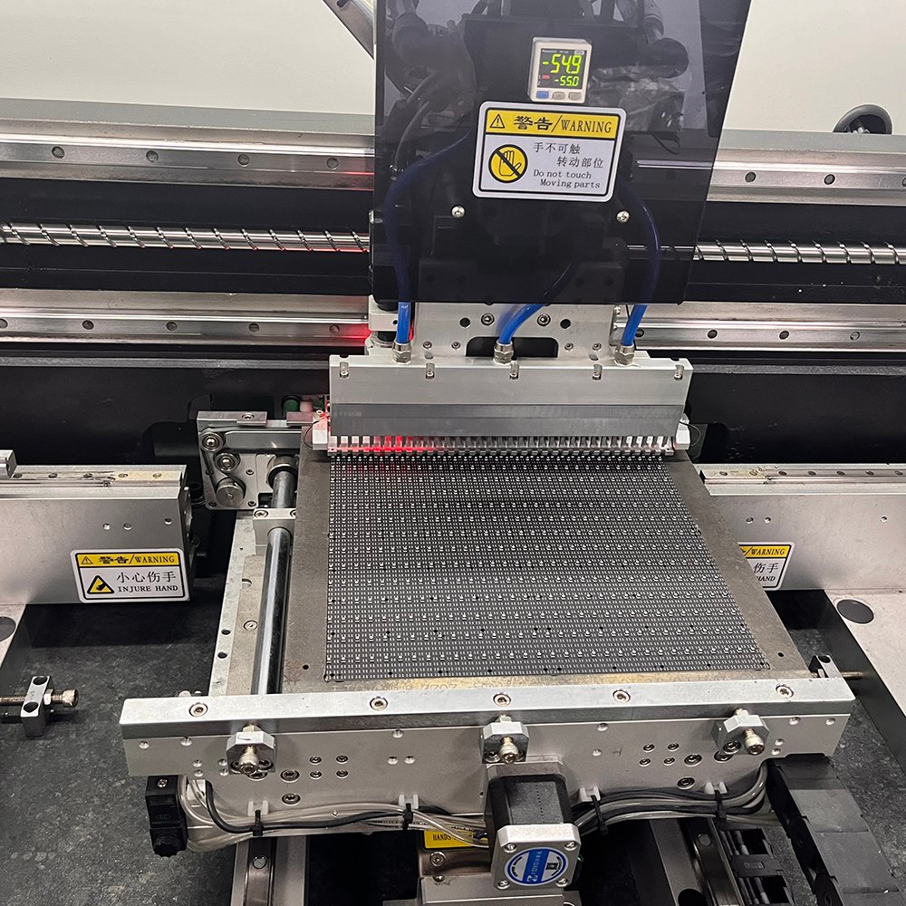
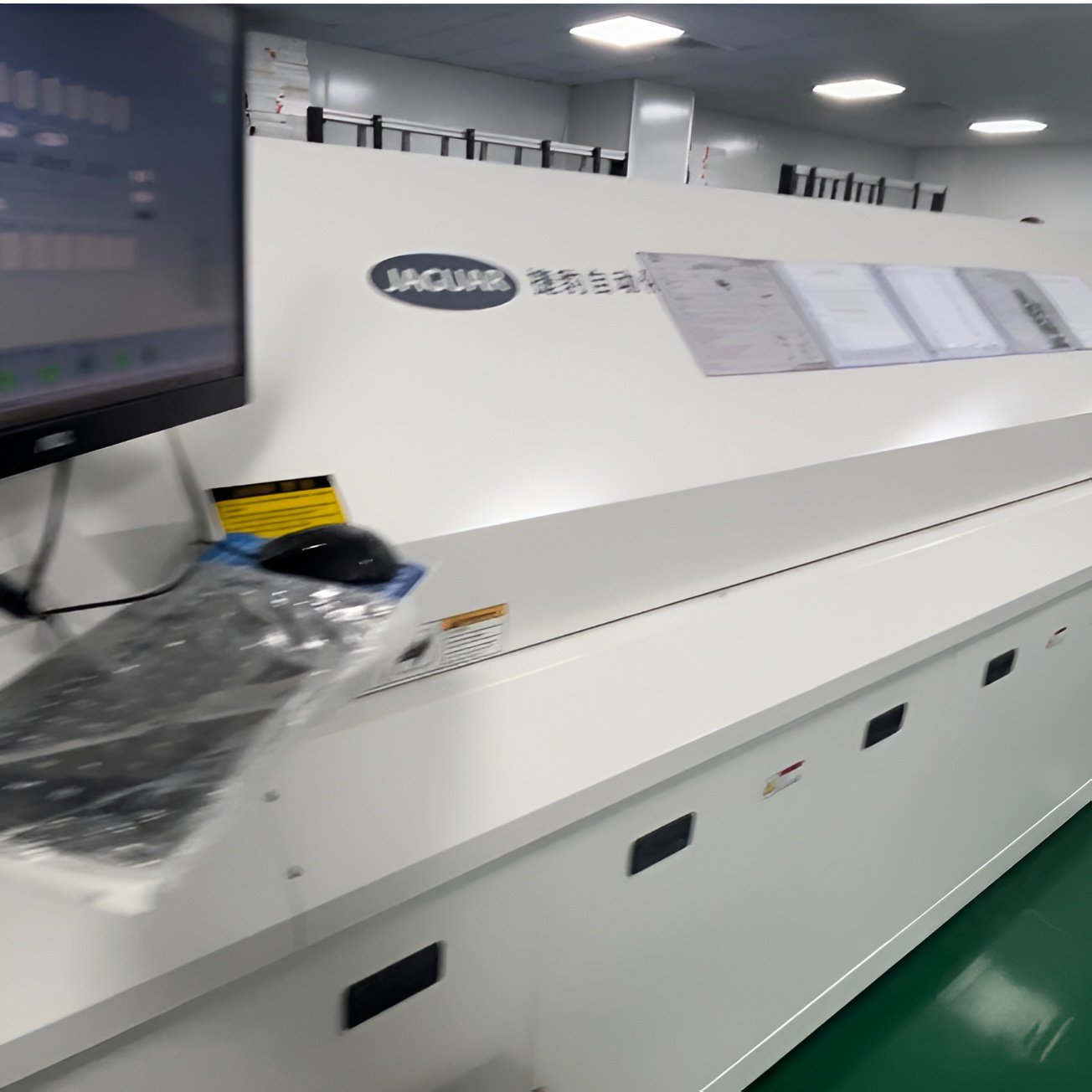
Use reflow soldering to fix the leds, ICs, capacitors and resistors on the circuit board.
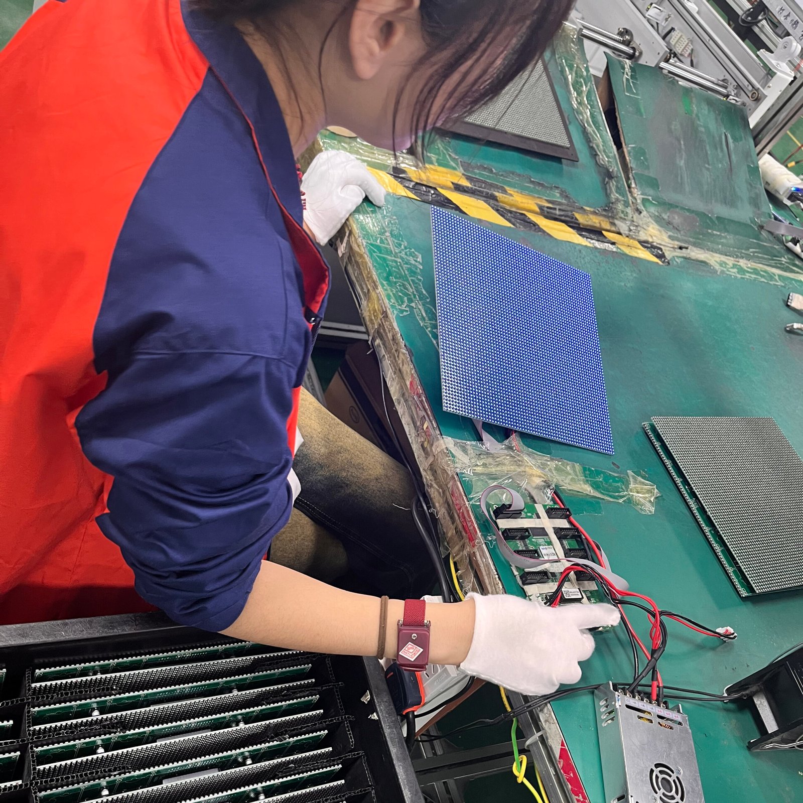
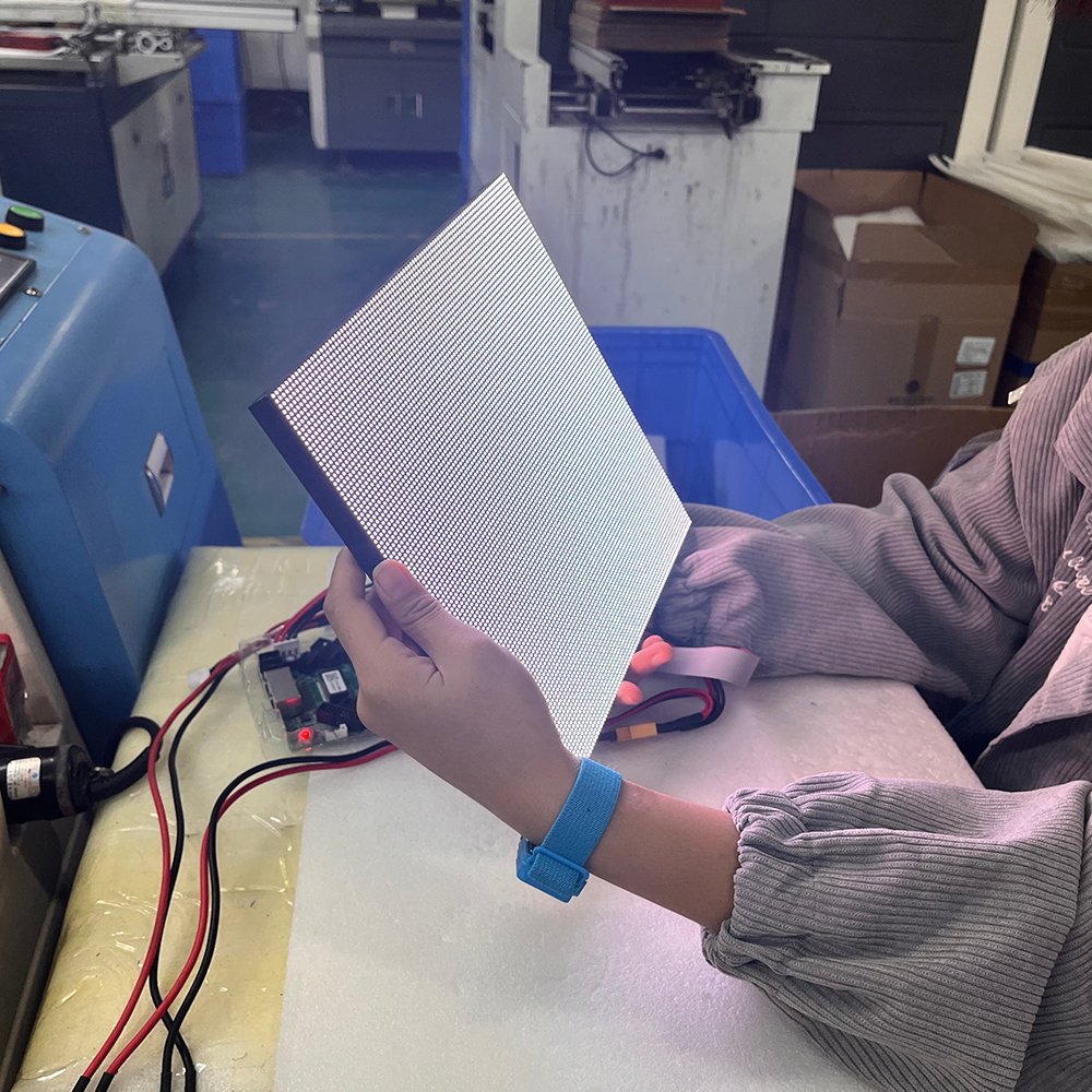
To ensure quality assurance,after fixing all components to circuit board, Will manually test the performance of LED modules.
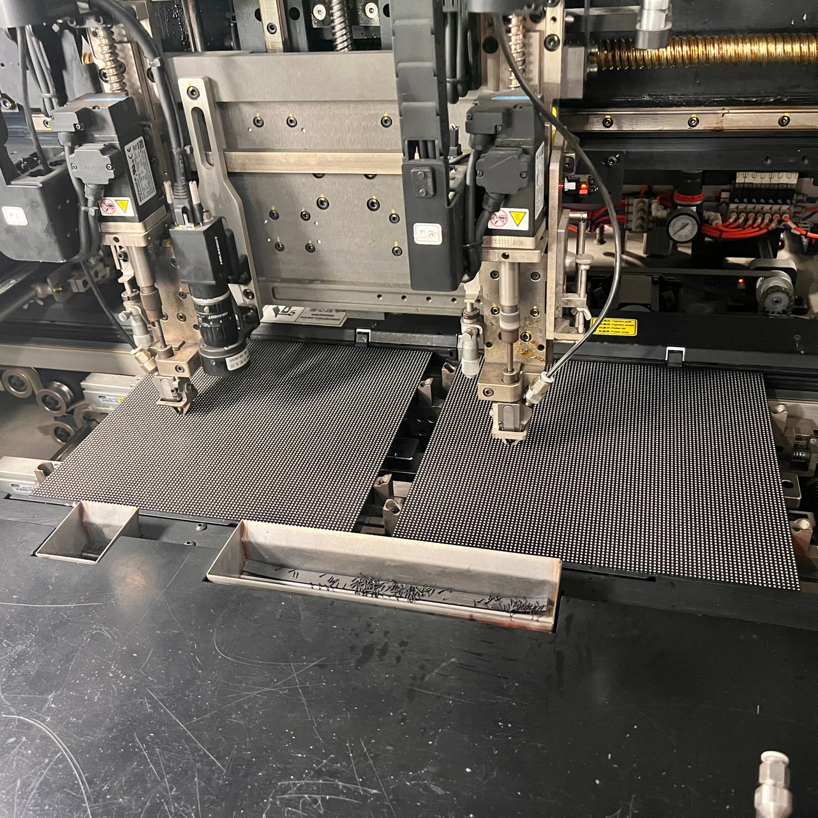
Automatic Screw Machine: Use the screw machine to fix the circuit board with the bottom shell.
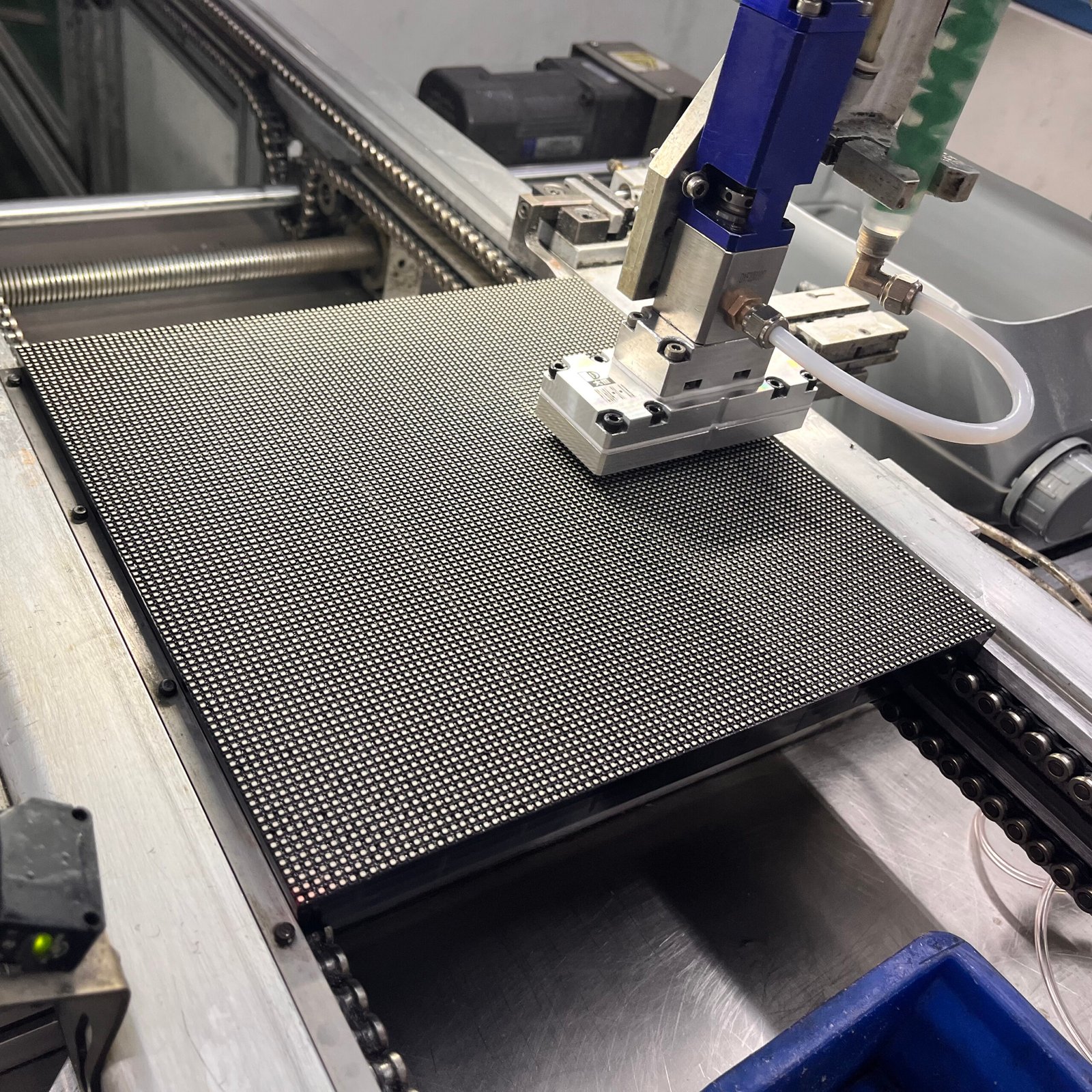
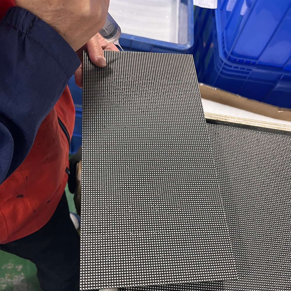
Automatic glue machine: Using an automatic glue machine to glue outdoor LED screen modules to achieve IP65 waterproof level.
The third door to quality assurance:Check the sealing condition of each module to ensure 100% waterproofing of the product.
The fourth step in quality assurance is to manually test the performance of the finished LED screen module.
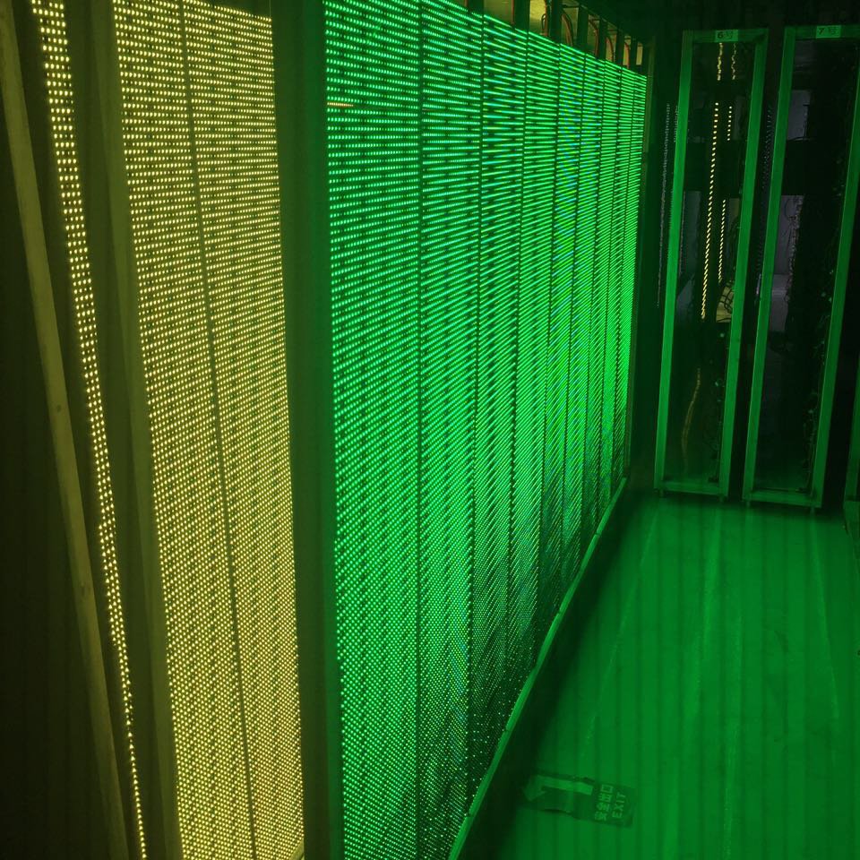
Aging test: The finished led screen module undergoes a 48 hours aging test to ensure product quality.
WhatsApp us
We will contact you within 1 working day, please pay attention to the email with the suffix”@dhxsigns.com“.
We will contact you within 1 working day, please pay attention to the email with the suffix”@dhxscreen.com“.
Fill out the form below, and we will be in touch shortly.